Imprecise Instructions Relating to Keyboard Design ️️
I recently completed my first hardware project: I designed and built a custom 22-key split keyboard.
Table of Contents:
Features of My Dream Keyboard
- Simple
- Looks Cool
- Adjustable Tenting ️
- Programmable Firmware
- Hot-swappable Switches
- Really Long Battery Life
- And BLE (Bluetooth Low Energy) Support
Hardware Design
This was my first PCB (printed circuit board), I made plenty of mistakes, but it works, and I learned a few things along the way. Most of the issues stem from habits that make me a good software developer. They are the antithesis of problems I've seen in source code written by electrical engineers, namely, too much abstraction (in my case) vs to little abstraction.
I opted for a sandwich case design, using blank PCBs as both the top and bottom plates. With an invertible core to reduce repetition and production costs.
Component Selection
Microcontroller
I'm using the nice!nano v2 for three reasons:
- It has a very low power draw.
- It's specifically designed for use in keyboards.
- There are already projects writing custom firmware for it.
I wanted the nice!nano to face the same direction on each half, so I added bridgeable jumper pads between the pins and connections. This allows me to solder pads on the underside of each board, putting the microcontroller on the top in both orientations. The solder pad is notched helping the surface tension of liquid solder bridge the gap.

This is where my issues with KiCad arose. I had traces running between pads on generic components throughout the board, e.g. traces connecting pins to each jumper pad. It seemed wrong to route these on the final PCB when they were inherently part of the footprint itself.
KiCad doesn't support routing traces within footprints, so I used "Edit Pad as Graphic Shapes" to create traces inside the footprint. This turned out to be a mistake. The approach broke KiCad's net handling and DRC (design rules checker), and the Edit Pads functionality itself is buggy. KiCad normally assigns and validates trace nets based on connected pad nets, but this logic fails when the traces are in fact pads. I also had to manually assign nets to these pad-based traces since they don't inherit nets from neighboring connections.


Switch Footprint
I chose the Cherry MX footprint, because it would give me the most diversity in switch selection. I used the same "Edit Pad as Graphic Shapes" functionality to connect the two positive pads (one on each side), reducing the amount of required routing in the final PCB:


Battery
I just chose the largest that would fit in between the columns. Lithium Polymer Batteries are labeled by size in the format: [XX][YY][ZZ]
- XX: Thickness (mm/10)
- YY: Width (mm)
- ZZ: Height (mm)
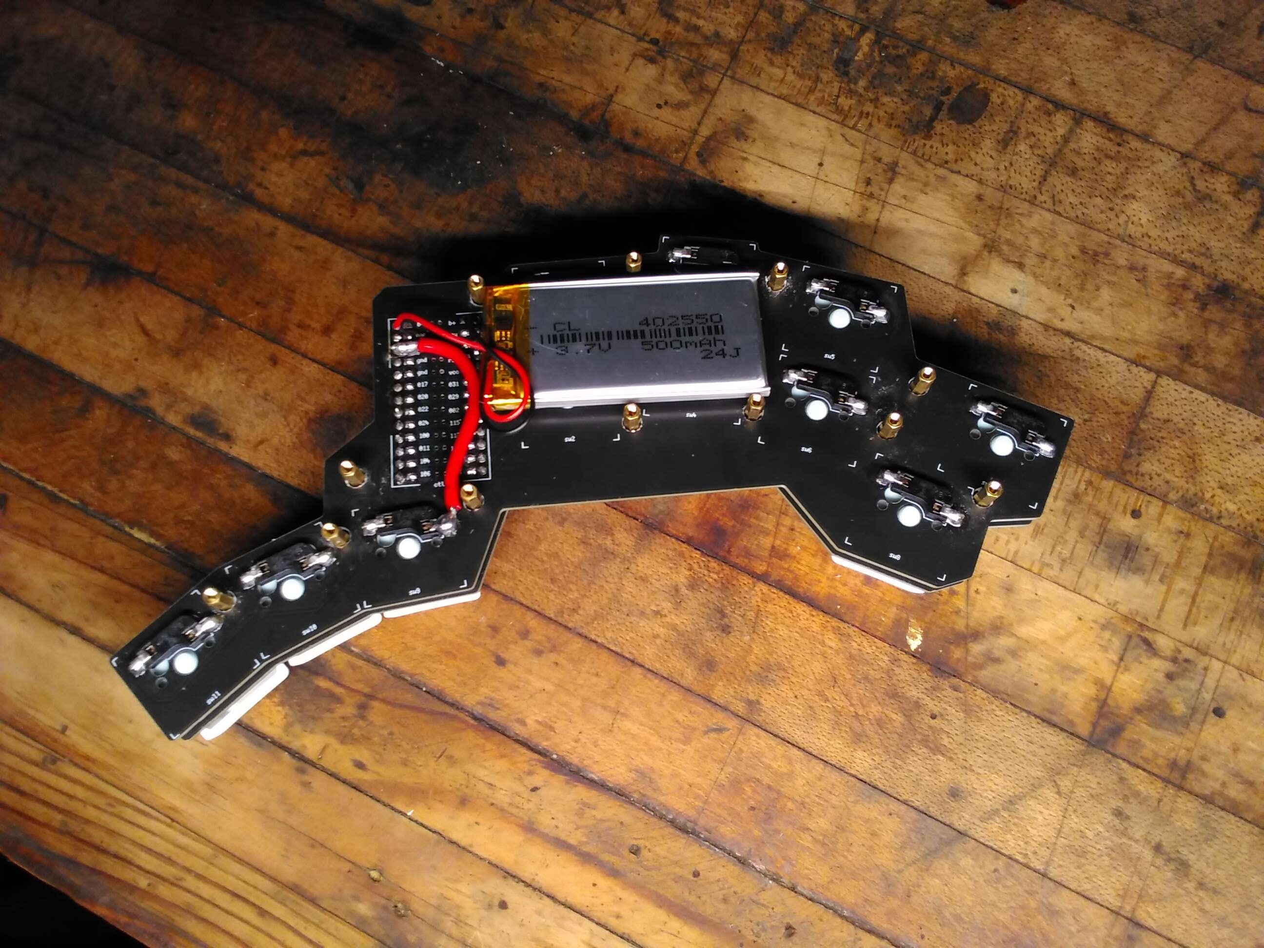
In my case the largest continuous space I could find was 4.0mm x 25mm x 50mm, so I choose a 3.7v 402550 Lithium Polymer Battery which is ~500mAh.
Key Positions ️
I sketched the key positions with pen and paper, which allowed faster iteration than KiCad and my printer would have. To transcribe the diagram into KiCad I used my micrometer to measure the distance from a few reference points, then placed circles at each reference point with radii equivalent to the measurements. The components could then be placed at the intersections of those circles.

These circles were used to align the corners of the switch on the far right.
Circuit Board
I then assembled these footprints connecting the inputs and outputs together; like calling functions to build the final board. It should be noted I misread the standoff diameter, so the through holes needed to be drilled out further by hand:


I then used the Edge.Cuts layer to make the top and bottom plates:


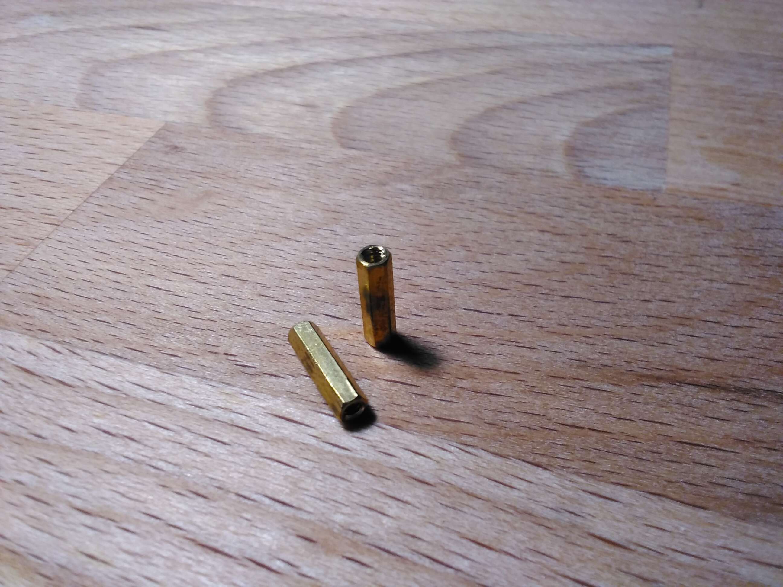
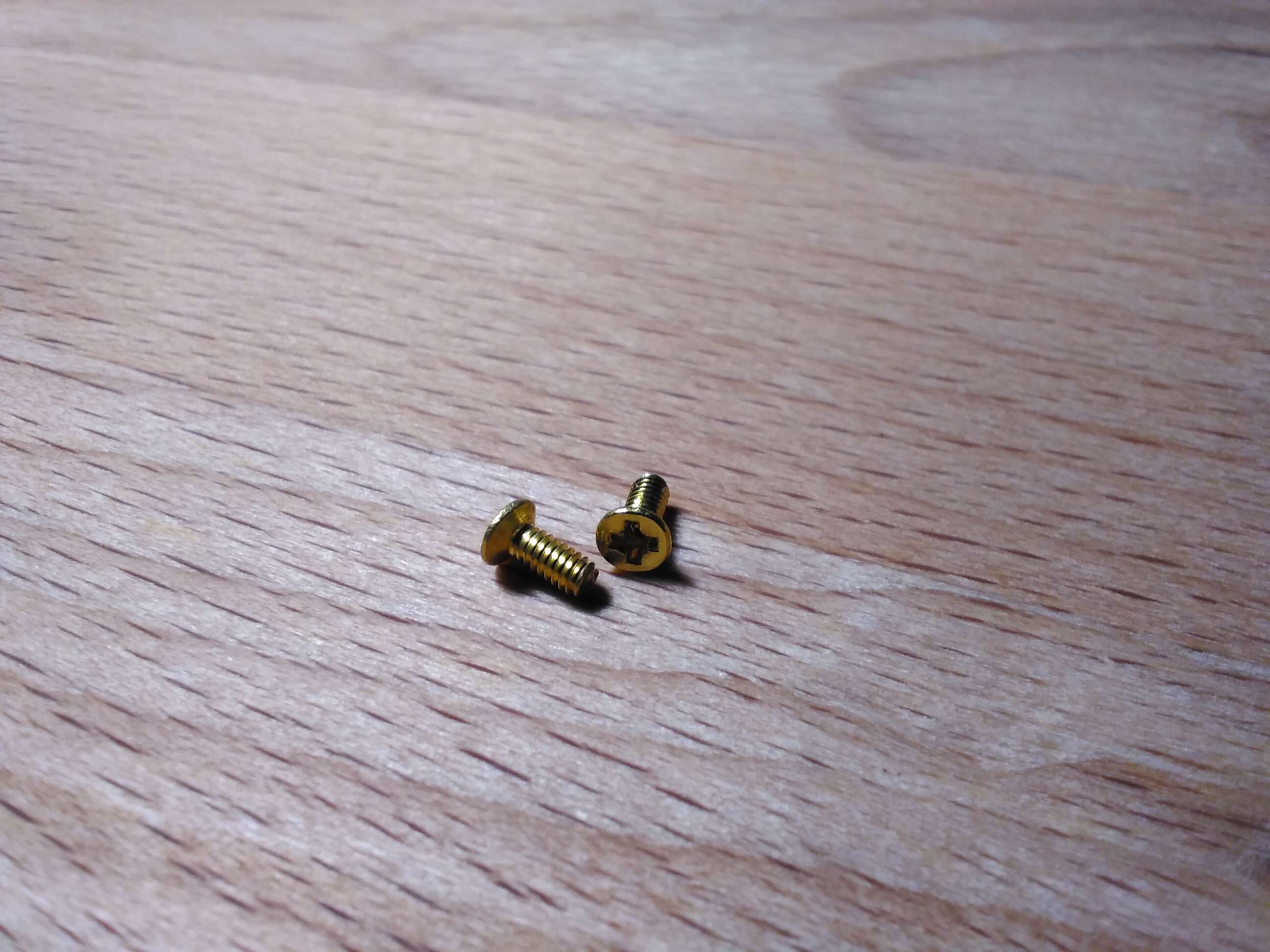
The top and bottom plates are connected via 2M, 11mm spacers and 2M, 5mm screws:
Then the core PCB is suspended in-between via the hot-swappable connections to the top plate.
Adjustable Tenting ️
I used the solution from this video by Joshua Blais. After sanding both surfaces, I glued the nut to the back of the PCB using some leftover marine epoxy... I didn't trust the Gorilla Tape idea.
Software Design
Ideally I'd like to develop my own firmware for this keyboard, the main reason being the connection architecture. Most easily customizable firmware, namely, ZMK / Zephyr Mechanical Keyboard Firmware, uses a primary and secondary keyboard model. The primary maintains two BLE connections: one to the secondary (receiving and processing its inputs) and another to the user's device:
     ┌-----------┐
 ┌-> | My Device |
 |   └-----------┘
 |
 |   ┌------------------┐     ┌--------------------┐
 └-> | Primary Keyboard | <-> | Secondary Keyboard |
     └------------------┘     └--------------------┘
This causes the primary to drain its battery far faster than the secondary, increasing charging frequency despite the secondary having plenty of juice () remaining. The primary dies after about six weeks, while the secondary hasn't needed charging in four months. This could be mitigated by dynamically switching which microcontroller acts as primary based on remaining battery power. Unfortunately, I don't have time for that right now, so I'm using ZMK as a stopgap solution.
ZMK Module
Defining new keyboard hardware in ZMK is fairly straightforward. The file structure looks like this:
.
├── boards
│   └── shields
│       └── franxx
│           ├── Kconfig.defconfig
│           ├── Kconfig.shield
│           ├── franxx.dtsi
│           ├── franxx.keymap
│           ├── franxx.zmk.yml
│           ├── franxx_left.overlay
│           └── franxx_right.overlay
├── build.yaml
├── config
│   └── west.yml
└── zephyr
    └── module.yml
Build System ️
A GitHub actions runner is usually used to generate firmware files, the build.yaml file defines the action's matrix:
# This file generates the GitHub Actions matrix.
# For simple board + shield combinations, add them to the top level board and
# shield arrays, for more control, add individual board + shield combinations
# to the `include` property. You can also use the `cmake-args` property to
# pass flags to the build command, `snippet` to add a Zephyr snippet, and
# `artifact-name` to assign a name to distinguish build outputs from each other:
#
# board: [ "nice_nano_v2" ]
# shield: [ "corne_left", "corne_right" ]
# include:
#   - board: bdn9_rev2
#   - board: nice_nano_v2
#     shield: reviung41
#   - board: nice_nano_v2
#     shield: corne_left
#     snippet: studio-rpc-usb-uart
#     cmake-args: -DCONFIG_ZMK_STUDIO=y
#     artifact-name: corne_left_with_studio
#
---
include:
  - board: nice_nano_v2
    shield: franxx_left
  - board: nice_nano_v2
    shield: franxx_right
The west command-line tool is a helper for the Zephyr RTOS (real-time operating system). Its configuration resides in config/west.yml:
manifest:
  defaults:
    revision: v0.3
  remotes:
    - name: zmkfirmware
      url-base: https://github.com/zmkfirmware
    # Additional modules containing boards/shields/custom code can be listed here as well
    # See https://docs.zephyrproject.org/3.2.0/develop/west/manifest.html#projects
  projects:
    - name: zmk
      remote: zmkfirmware
      import: app/west.yml
  self:
    path: config
The Zephyr module is defined in zephyr/module.yml:
name: zmk-keyboard-franxx

build:
  settings:
    board_root: .
Shield ️
The shield defines the hardware interface and defaults for a given keyboard design. Shields are stored in the boards/shields/<your_keyboard_name> directory and aren't modified by ordinary users.
Metadata
In franxx.zmk.yml we define ZMK-related metadata (this would probably be important if I were ever pushing this shield upstream):
file_format: "1"
id: franxx
name: franxx
type: shield
url: https://github.com/5-pebbles/franxx
requires:
  - pro_micro
features:
  - keys
siblings:
  - franxx_left
  - franxx_right
Kconfig
The Kconfig.shield file contains Kconfig declarations that define the shield as a selectable option within the build system:
# This creates two boolean config options (one for each half of the split keyboard).
# The def_bool with shields_list_contains automatically sets these to true when the corresponding shield name is specified in the build.

config SHIELD_FRANXX_LEFT
    def_bool $(shields_list_contains,franxx_left)

config SHIELD_FRANXX_RIGHT
    def_bool $(shields_list_contains,franxx_right)
Kconfig.defconfig sets default Kconfig values used when this shield is selected:
if SHIELD_FRANXX_LEFT

# Name must be less than 16 characters long!
config ZMK_KEYBOARD_NAME
    default "FRANXX"

config ZMK_SPLIT_ROLE_CENTRAL
    default y

endif

if SHIELD_FRANXX_LEFT || SHIELD_FRANXX_RIGHT

config ZMK_SETTINGS_RESET_ON_START
    default y

config ZMK_POINTING
    default y

config USB_DEVICE_MANUFACTURER
    default "Owen Friedman"

config BT_DIS_MANUF
    default "Owen Friedman"

config ZMK_SPLIT
    default y

endif
Device Tree Source
The franxx.dtsi file defines the hardware device tree source, what triggers key presses and the keymap layout. Using the nice!nano pinout we can map physical pins to GPIO ports and pin numbers:
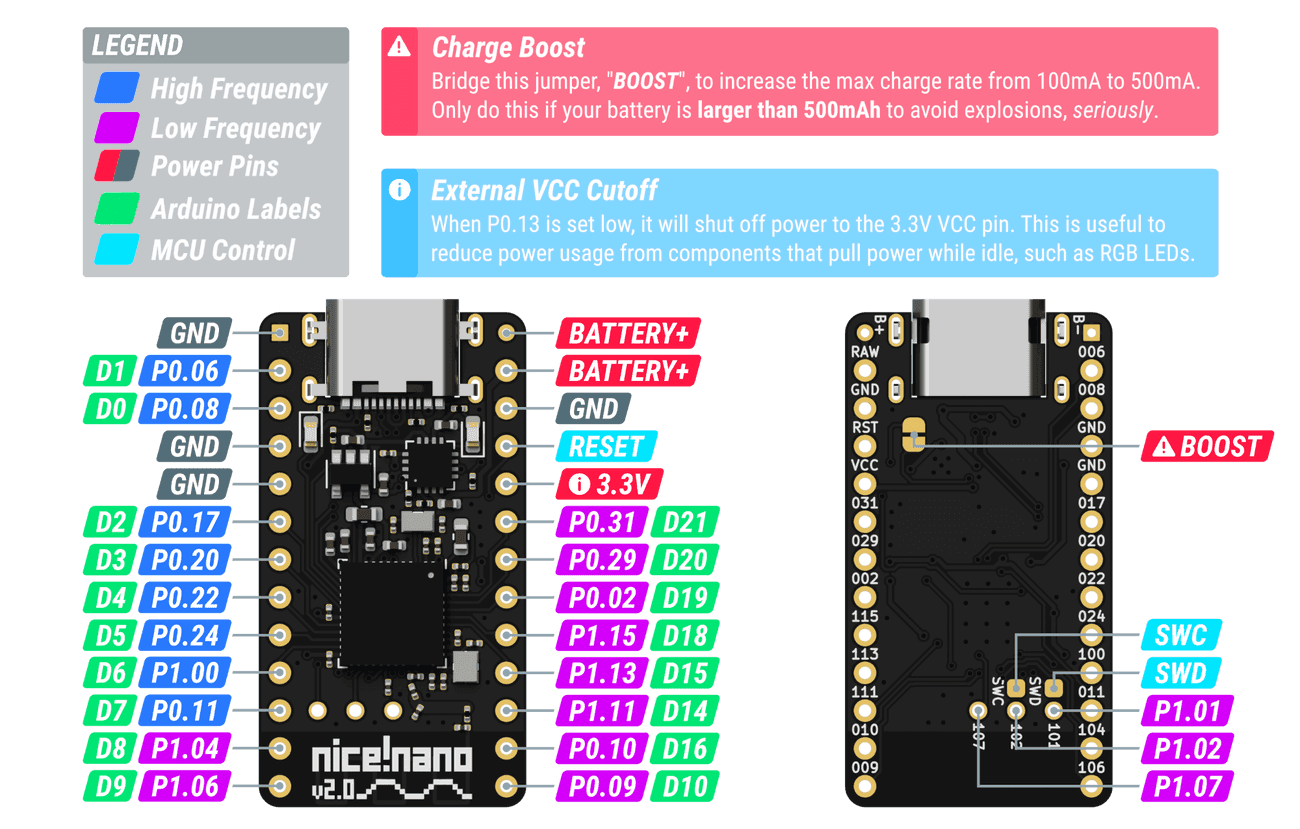
Pinout diagram from Nice Technologies LLC, used under fair use.
The kscan0 node defines hardware scanning. "zmk,kscan-gpio-direct" disables matrix scanning, mapping each pin to its own key:
#include <dt-bindings/zmk/matrix_transform.h>

/ {
  kscan0: kscan0 {
    compatible = "zmk,kscan-gpio-direct";
    wakeup-source; // Wake the board on a keypress...
    input-gpios =
      <&gpio0 31 (GPIO_ACTIVE_LOW | GPIO_PULL_UP)>,
      <&gpio0 29 (GPIO_ACTIVE_LOW | GPIO_PULL_UP)>,
      <&gpio0  2 (GPIO_ACTIVE_LOW | GPIO_PULL_UP)>,
      <&gpio1 15 (GPIO_ACTIVE_LOW | GPIO_PULL_UP)>,
      <&gpio1 13 (GPIO_ACTIVE_LOW | GPIO_PULL_UP)>,
      <&gpio1 11 (GPIO_ACTIVE_LOW | GPIO_PULL_UP)>,
      <&gpio0 10 (GPIO_ACTIVE_LOW | GPIO_PULL_UP)>,
      <&gpio0  9 (GPIO_ACTIVE_LOW | GPIO_PULL_UP)>,
      <&gpio1  6 (GPIO_ACTIVE_LOW | GPIO_PULL_UP)>,
      <&gpio0 11 (GPIO_ACTIVE_LOW | GPIO_PULL_UP)>,
      <&gpio1  4 (GPIO_ACTIVE_LOW | GPIO_PULL_UP)>;
  };
Each of our physical keys connects a GPIO pin to ground when pressed. The GPIO_PULL_UP flag sets each pin in a pull-up configuration, where the pin is connected to vcc through a resistor, causing measurements to read high by default.
When the key is pressed and ground is bridged, there's no longer any resistance (the current simply flows to ground) and thus voltage measurements will read low.

The GPIO_ACTIVE_LOW flag tells ZMK to trigger a key press when the pin's voltage reads low.
The default_transform node maps physical GPIO pins to logical key positions in the keymap. I define a single-row matrix with 22 columns using "zmk,matrix-transform":
  default_transform: keymap_transform_0 {
      compatible = "zmk,matrix-transform";
      columns = <22>;
      rows = <1>;
      map = <
        RC(0,3)  RC(0,2)  RC(0,1)  RC(0,0)    RC(0,11) RC(0,12) RC(0,13) RC(0,14)
        RC(0,4)  RC(0,5)  RC(0,6)  RC(0,7)    RC(0,18) RC(0,17) RC(0,16) RC(0,15)
                 RC(0,8)  RC(0,9)  RC(0,10)   RC(0,21) RC(0,20) RC(0,19)
      >;
  };
The map property uses RC(row, column) macros to specify the matrix coordinate for each physical key position. Since we're using direct GPIO scanning (not a matrix), we have a single row (row 0) with each key assigned a unique column index.
NOTE: The column indices can be offset for the right keyboard in a following overlay file.
The physical_layout0 node binds the hardware scanning configuration to the keymap transformation:
  physical_layout0: physical_layout_0 {
    compatible = "zmk,physical-layout";
    display-name = "Default Layout";
    kscan = <&kscan0>;
    transform = <&default_transform>;
  };
This links our kscan0 hardware scanner with the default_transform coordinate mapping, creating a complete physical layout definition.
Finally, the chosen node tells ZMK which physical layout to use at runtime:
  chosen {
    zmk,physical-layout = &physical_layout0;
    // Other chosen items
  };
};
Overlays
Both the franxx_left.overlay and franxx_right.overlay files are device tree overlay nodes. They allow per-board device tree modifications using references to previously defined nodes:
// FRANXX Left has no modifications to the device tree...
#include "franxx.dtsi"
// FRANXX Right has all GPIO offset by 11, e.g. input on column (GPIO pin index) #0 -> #11.
#include "franxx.dtsi"

&default_transform {
    col-offset = <11>;
};
Key Map ️
That covers everything except franxx.keymap, which normally stores the default keymap. I'm just defining my personal layout there since there's no point in defining defaults when I'll be the only user.
The layout definitely needs optimization, but I'm back up to ~80wpm, which is good enough for now. Since it uses the same syntax as every other ZMK layout, I'll just link to the ZMK docs:
#include <behaviors.dtsi>
#include <dt-bindings/zmk/bt.h>
#include <dt-bindings/zmk/keys.h>
#include <dt-bindings/zmk/outputs.h>
#include <dt-bindings/zmk/pointing.h>
#define ZMK_POINTING_DEFAULT_MOVE_VAL 1500
#define ZMK_POINTING_DEFAULT_SCRL_VAL 20
#define DEFAULT 0
#define ALT_ALPHA 1
#define SYM 2
#define NUM 3
#define CTRL 4
#define VIMCRAFT 5
/ {
behaviors {
tog_on: toggle_layer_on_only {
compatible = "zmk,behavior-toggle-layer";
#binding-cells = <1>;
display-name = "Toggle Layer On";
toggle-mode = "on";
};
tog_off: toggle_layer_off_only {
compatible = "zmk,behavior-toggle-layer";
#binding-cells = <1>;
display-name = "Toggle Layer Off";
toggle-mode = "off";
};
};
macros {
to_num: to_num {
compatible = "zmk,behavior-macro";
#binding-cells = <0>;
bindings
= <¯o_tap &to NUM>
, <¯o_tap &tog_on SYM>
;
};
};
combos {
compatible = "zmk,combos";
combo_nine_vimcraft {
timeout-ms = <50>;
key-positions = <6 7>; // positions of the `7` and `8` keys in vimcraft layer
bindings = <&kp N9>;
layers = <VIMCRAFT>; // only active on vimcraft layer
};
combo_to_default_vimcraft {
timeout-ms = <50>;
key-positions = <0 1>; // positions of the `1` and `2` keys in vimcraft layer
bindings = <&to DEFAULT>;
layers = <VIMCRAFT>; // only active on vimcraft layer
};
combo_scroll_up_vimcraft {
timeout-ms = <50>;
key-positions = <9 10>; // positions of the `S` and `W` keys in vimcraft layer
bindings = <&msc SCRL_UP>;
layers = <VIMCRAFT>; // only active on vimcraft layer
};
combo_scroll_down_vimcraft {
timeout-ms = <50>;
key-positions = <8 11>; // positions of the `A` and `D` keys in vimcraft layer
bindings = <&msc SCRL_DOWN>;
layers = <VIMCRAFT>; // only active on vimcraft layer
};
};
keymap {
compatible = "zmk,keymap";
default_layer {
bindings = <
// ┌---------┬---------┬---------┬---------┐ ┌---------┬---------┬---------┬---------┐
// │ B │ Y │ O │ U │ │ L │ D │ W │ V │
&kp B &kp Y &kp O &kp U &kp L &kp D &kp W &kp V
// │ C │ I │ E │ A │ │ H │ T │ S │ N │
&kp C &kp I &kp E &kp A &kp H &kp T &kp S &kp N
// └---------┼---------┼---------┼---------┤ ├---------┼---------┼---------┼---------┘
// │ ESC │ SPACE │ RSHFT │ │ sl │ sl │ BSPC │
&kp ESC &kp SPACE &kp RSHFT &sl SYM &sl ALT_ALPHA &kp BSPC
// └---------┴---------┴---------┘ └---------┴---------┴---------┘
>;
};
alt_alpha {
bindings = <
// ┌---------┬---------┬---------┬---------┐ ┌---------┬---------┬---------┬---------┐
// │ TAB │ ' │ , │ Z │ │ Q │ . │ ; │ RET │
&kp TAB &kp SQT &kp COMMA &kp Z &kp Q &kp DOT &kp SEMI &kp RET
// │ G │ X │ J │ K │ │ R │ M │ F │ P │
&kp G &kp X &kp J &kp K &kp R &kp M &kp F &kp P
// └---------┼---------┼---------┼---------┤ ├---------┼---------┼---------┼---------┘
// │ LCMD │ LCTRL │ LALT │ │ sl │ to_num │ ` │
&sk LCMD &sk LCTRL &sk LALT &sl CTRL &to_num &kp GRAVE
// └---------┴---------┴---------┘ └---------┴---------┴---------┘
>;
};
sym {
bindings = <
// ┌---------┬---------┬---------┬---------┐ ┌---------┬---------┬---------┬---------┐
// │ # │ | │ [ │ ] │ │ & │ * │ / │ ! │
&kp POUND &kp PIPE &kp LBKT &kp RBKT &kp AMPS &kp ASTRK &kp FSLH &kp EXCL
// │ ( │ ) │ { │ } │ │ = │ + │ - │ ? │
&kp LPAR &kp RPAR &kp LBRC &kp RBRC &kp EQUAL &kp PLUS &kp MINUS &kp QMARK
// └---------┼---------┼---------┼---------┤ ├---------┼---------┼---------┼---------┘
// │ DEL │ ~ │ _ │ │ \ │ ^ │ @ │
&kp DEL &kp TILDE &kp UNDER &kp BSLH &kp CARET &kp AT
// └---------┴---------┴---------┘ └---------┴---------┴---------┘
>;
};
num {
bindings = <
// ┌---------┬---------┬---------┬---------┐ ┌---------┬---------┬---------┬---------┐
// │ 7 │ 6 │ 5 │ 4 │ │ % │ trans │ trans │ to_sym │
&kp N7 &kp N6 &kp N5 &kp N4 &kp PRCNT &trans &trans &none
// │ 3 │ 2 │ 1 │ 0 │ │ trans │ trans │ trans │ to_def │
&kp N3 &kp N2 &kp N1 &kp N0 &trans &trans &trans &none
// └---------┼---------┼---------┼---------┤ ├---------┼---------┼---------┼---------┘
// │ 9 │ 8 │ trans │ │ to │ trans │ BSPC │
&kp N9 &kp N8 &trans &to DEFAULT &trans &kp BSPC
// └---------┴---------┴---------┘ └---------┴---------┴---------┘
>;
};
ctrl {
bindings = <
// ┌---------┬---------┬---------┬---------┐ ┌---------┬---------┬---------┬---------┐
// │ F8 │ F7 │ F6 │ F5 │ │ F4 │ F3 │ F2 │ F1 │
&kp F8 &kp F7 &kp F6 &kp F5 &kp F4 &kp F3 &kp F2 &kp F1
// │ C_PWR │ C_MUTE │ VOL_DN │ VOL_UP │ │ F12 │ F11 │ F10 │ F9 │
&kp C_PWR &kp C_MUTE &kp C_VOL_DN &kp C_VOL_UP &kp F12 &kp F11 &kp F10 &kp F9
// └---------┼---------┼---------┼---------┤ ├---------┼---------┼---------┼---------┘
// │ BT_PRV │ BT_NXT │ BT_CLR │ │ OUT_USB │ OUT_BLE │ to │
&bt BT_PRV &bt BT_NXT &bt BT_CLR &out OUT_USB &out OUT_BLE &to VIMCRAFT
// └---------┴---------┴---------┘ └---------┴---------┴---------┘
>;
};
vimcraft {
bindings = <
// ┌---------┬---------┬---------┬---------┐ ┌---------┬---------┬---------┬---------┐
// │ 1 │ 2 │ 3 │ 4 │ │ 5 │ 6 │ 7 │ 8 │
&kp N1 &kp N2 &kp N3 &kp N4 &kp N5 &kp N6 &kp N7 &kp N8
// │ A │ S │ W │ D │ │ LEFT │ DOWN │ UP │ RIGHT │
&kp A &kp S &kp W &kp D &mmv MOVE_LEFT &mmv MOVE_DOWN &mmv MOVE_UP &mmv MOVE_RIGHT
// └---------┼---------┼---------┼---------┤ ├---------┼---------┼---------┼---------┘
// │ SPACE │ LCLK │ F │ │ E │ RCLK │ LSHFT │
&kp SPACE &mkp LCLK &kp F &kp E &mkp RCLK &kp LSHFT
// └---------┴---------┴---------┘ └---------┴---------┴---------┘
>;
};
};
};
The best part of this whole thing is playing Minecraft without a mouse, hence the dedicated layer.
Bugs in the Wallpaper
As one would expect with my first circuitry-related project, there were plenty of issues. I've excluded all the software related problems since those were easily amended.
Where's the Ground? ️
Long story short: I have no idea, but there's no continuity between any of the microcontrollers three ground pins and the ground plane. ¯\(-_-)/¯
...
Yeah, not sure how I missed this one:


The fix was straightforward, I ran a wire from a ground pin to the ground pad of the nearest key.
It should be noted this is one of those things the DRC should have caught, but couldn't because of my abuse of pads as traces.
Microcontroller Clearance
For some reason I thought it would be a good idea to guesstimate the clearance on the microcontroller and upper plate. That went about as well as you'd expect:
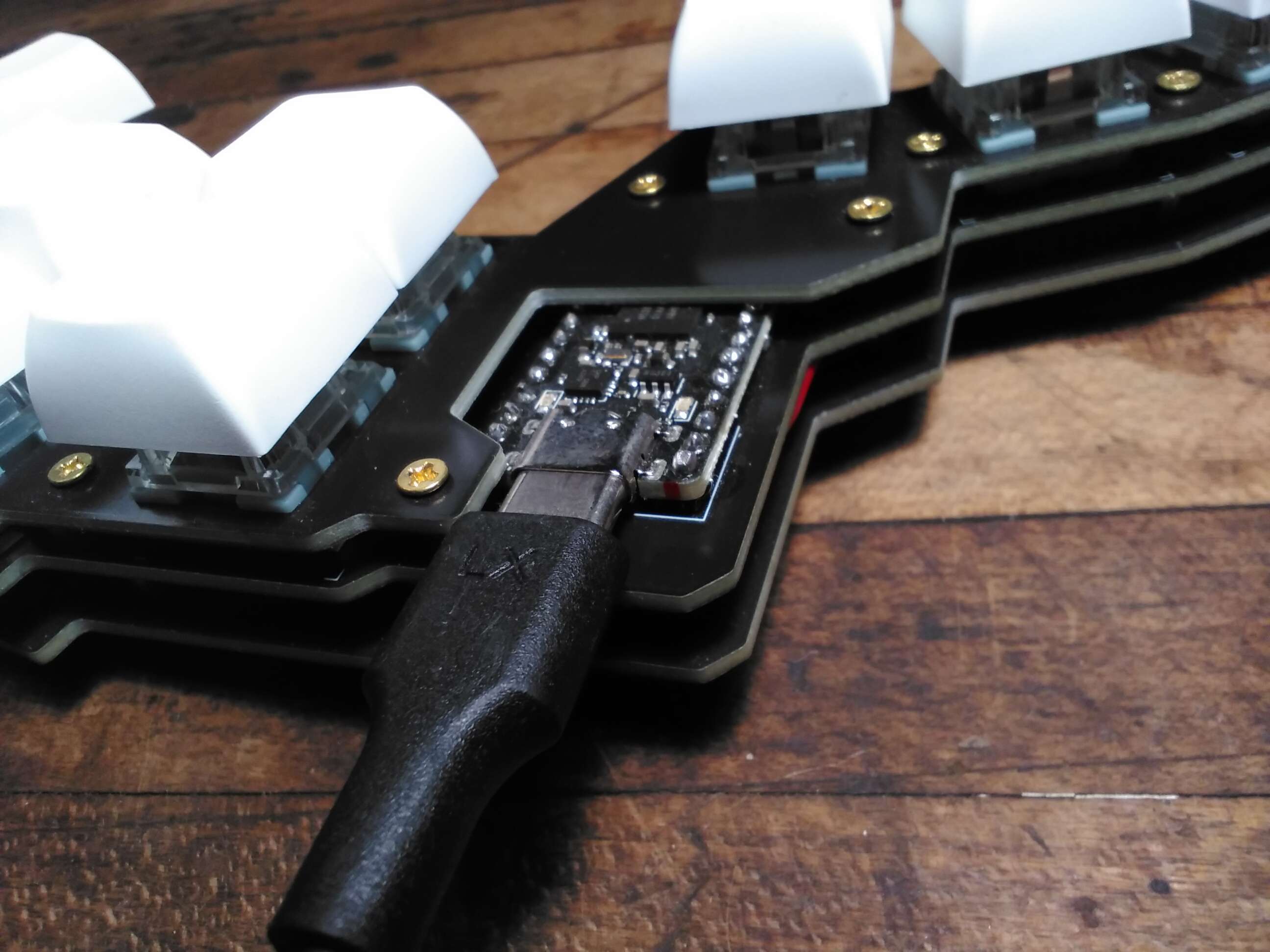
There isn't enough space to plugin most USB-C connectors, they are all too wide. That said I have one cable thin enough to fit, so we're all good ().
Power Off
The other self-inflicted issue is that the battery needs to be soldered directly to the microcontroller. In and of itself I don't mind this, but the nice!nano has through-hole pads for the battery connections, which fill with solder after the first connection. This makes power cycling a 30-minute ordeal all to save the cost and complexity of a JST XH 2.54mm connector (two of them cost 75 cents...)..
Thankfully fixing this just involves de-soldering the battery and replacing it with the aforementioned 37.5-cent connectors.
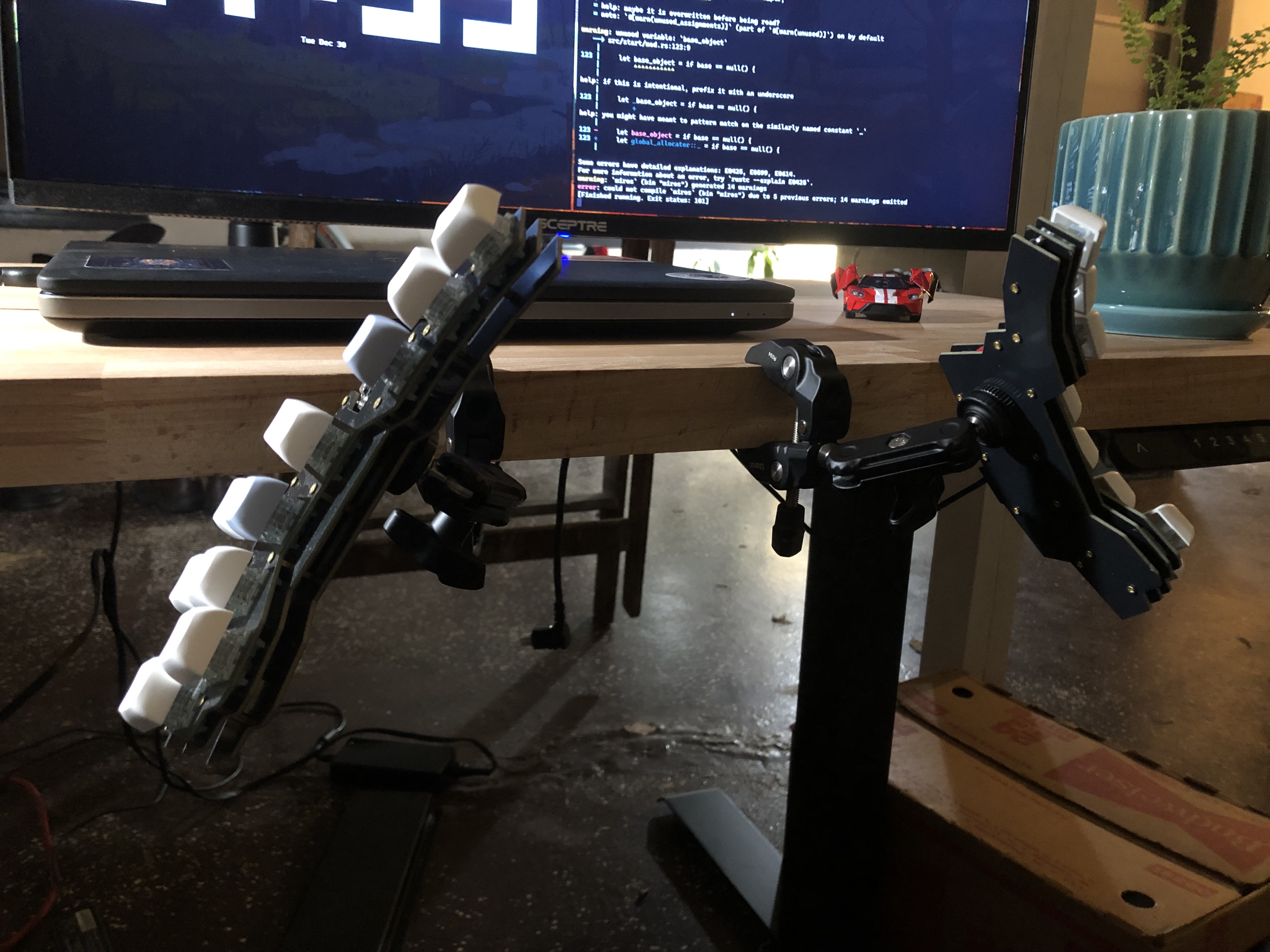
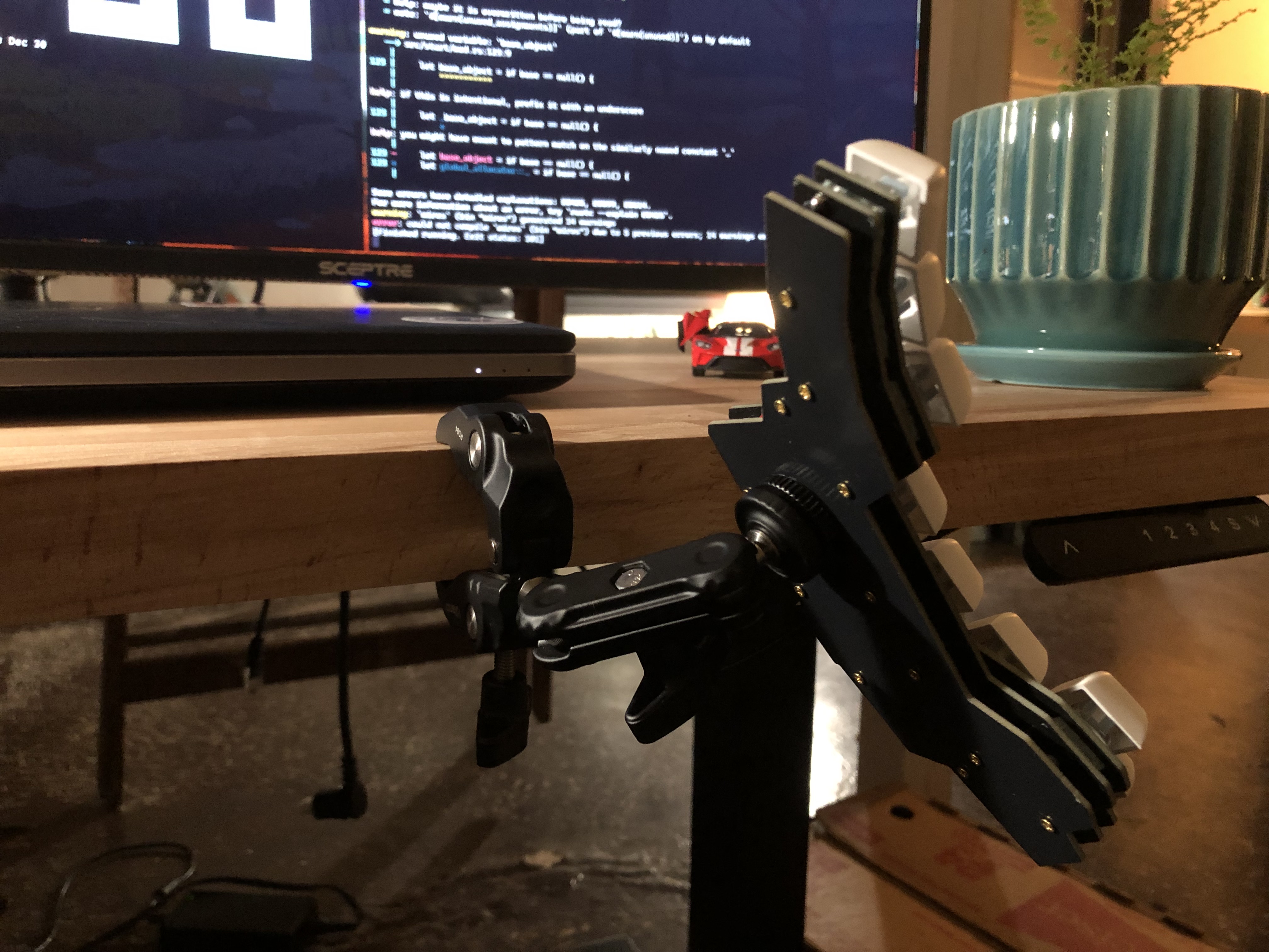
Quod Erat Demonstrandum
While this is pretty trivial compared to real-world projects I've seen, it was a good starting point. I learned the tooling and design philosophy needed for slightly larger projects, plus I got a pretty sweet keyboard out of it:
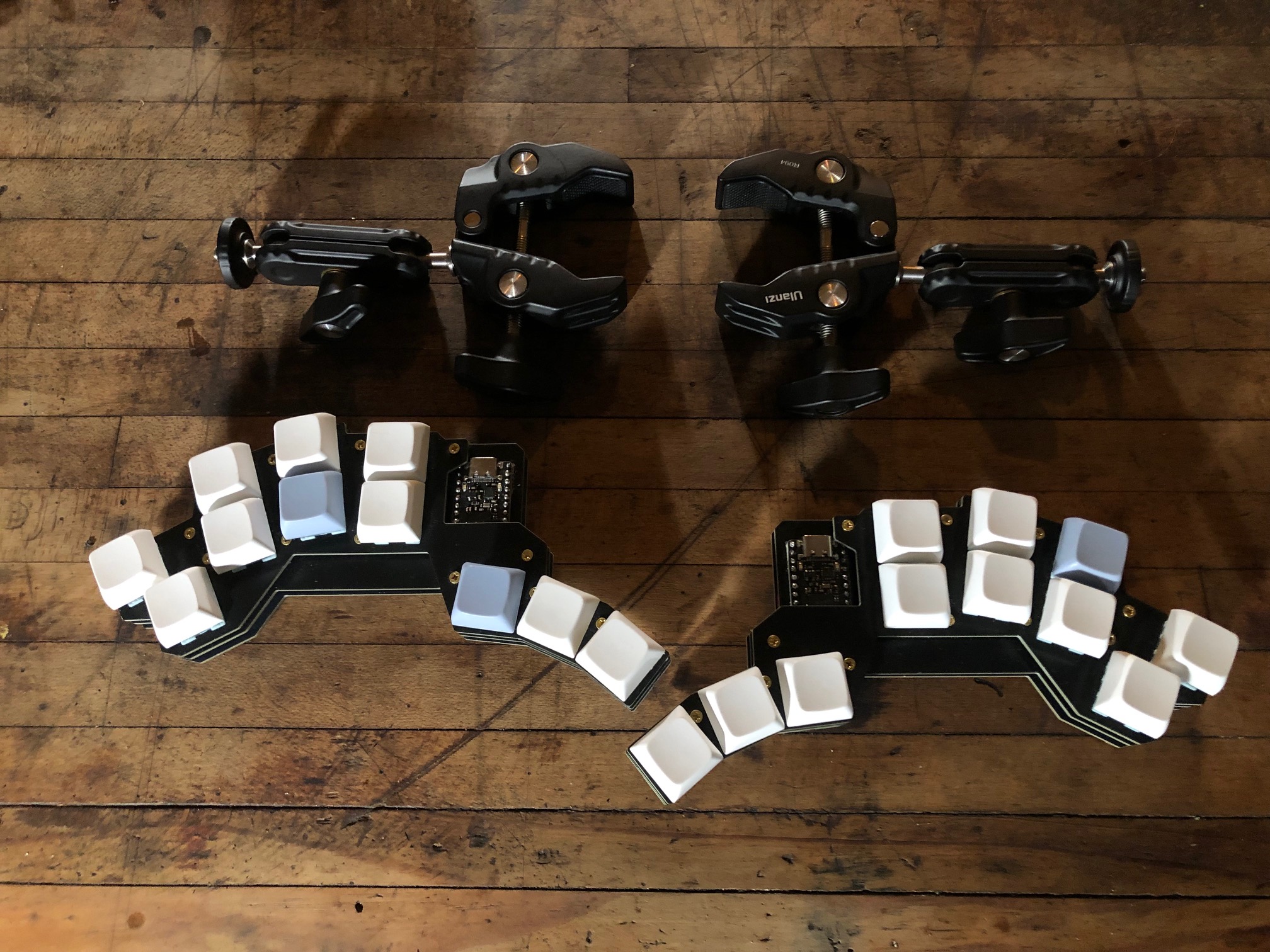
You've reached the end of this adventure, see y'all next time! ʕ•ᴥ•ʔ